|
|  |
|


 radar
radar
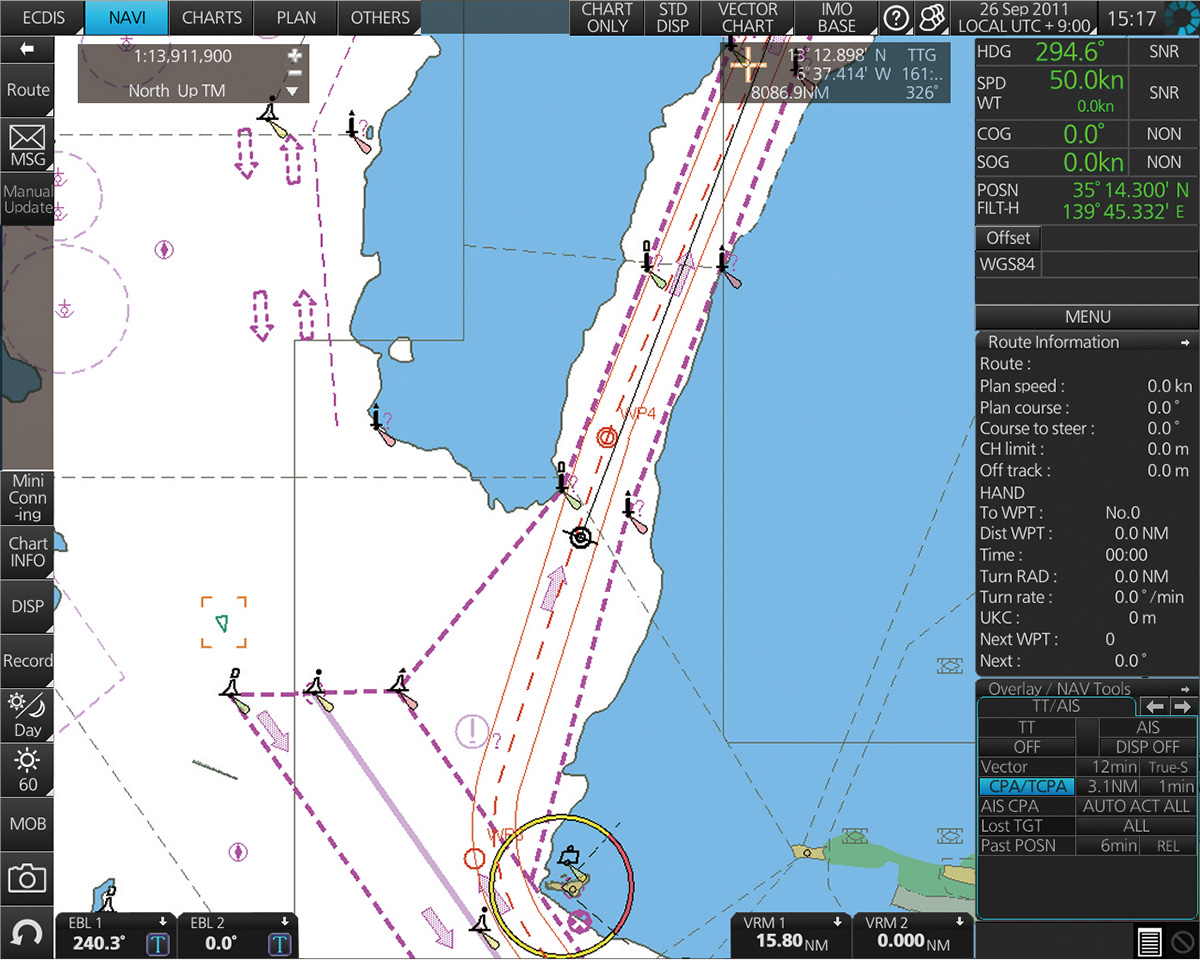 ECDIS
ECDIS
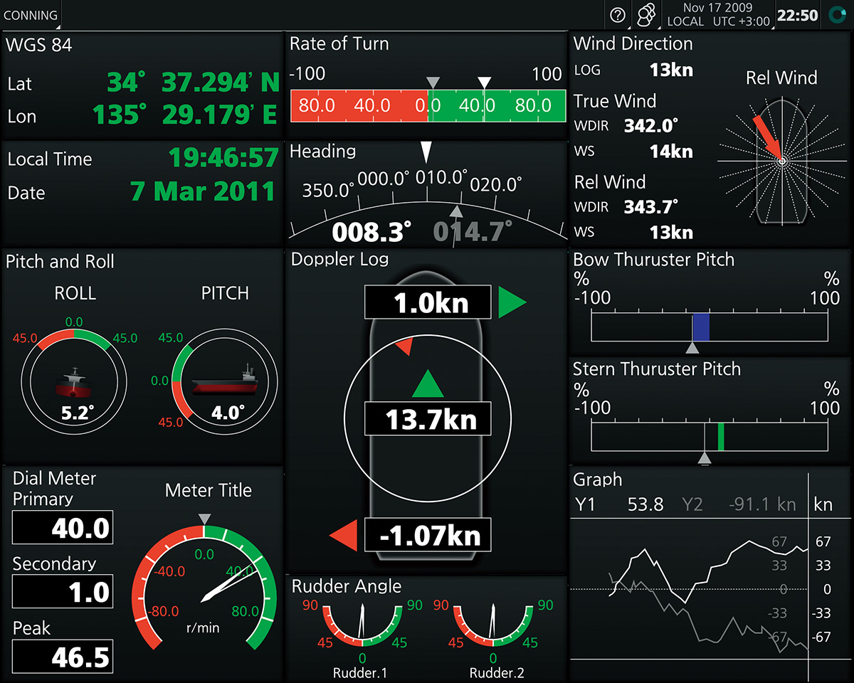 Conning
* Radar sensors need to be connected to the network.
** The display function of radar and alarm management system will be implemented as software update after product release. (option)
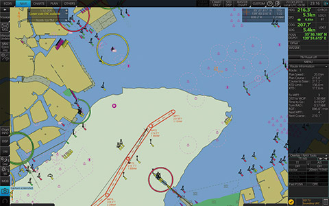
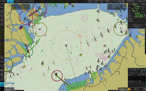
Real-time redrawing of charts
The intuitive new user interface can quickly and accurately manage route planning, monitoring and navigation data.
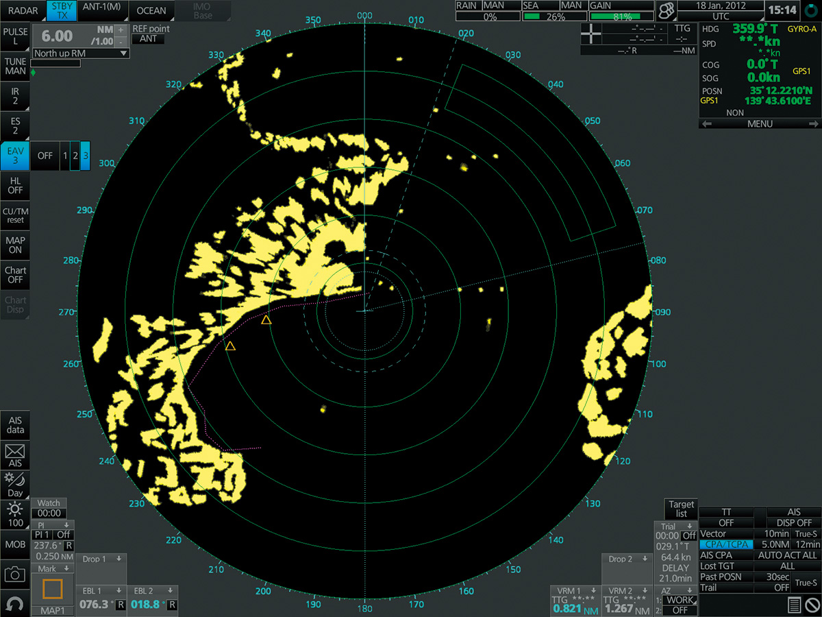
The interface is equipped with existing FAR-21x7/FAR28x7 series radars. Radar image overlay display, target tracking information, route and route point exchange can be carried out through ethernet.
Fully meet the requirements of IMO and IEC standards and specifications:
IMO MSC.232(82)
IMO A.694(17)
IEC 61174 Ed. 3
IEC 61162-1 Ed. 4
IEC 61162-2 Ed. 1
IEC 62288
IHO/S-57 Version 3 Vector Chart (IHO S-63 Data Protection Scheme)
AVCS provided by UKHO (Admiralty Vector Chart Service)
C-MAP ENC
Jeppesen Primar ECDIS service
ARCS Raster Chart
C-MAP Professional+*
*C-MAP Professional+ It belongs to unofficial charts, so it can not be regarded as a substitute for paper charts.
The additional AIO layer includes all "temporary and preliminary announcements" and the additional ENC preliminary announcements, i.e. the navigation hazards reported in paper charts but not in electronic charts. As part of AVCS provided by UKHO, this service is free of charge.
Electronic nautical charts
Raster Chart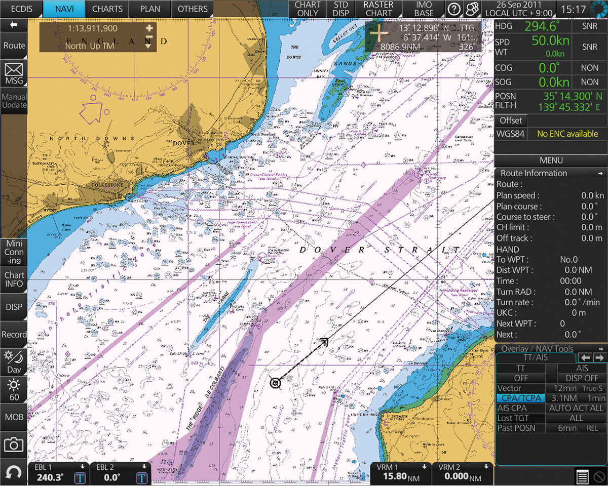
AIO Data Layer Display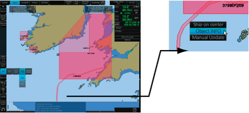
Move the cursor to the AIO target, then right-click to open the context menu. Select'target information'and open the chart target window.
Chart Target Window
Chart Target Window
Select the AIO target in the chart target wind
Move the cursor to the AIO target, then right-click to open the context menu. Select'target information'and open the chart target window.
Chart Target Window
Chart Target Window
Select the AIO target in the chart target wind
Move the cursor to the AIO target, then right-click to open the context menu. Select'target information'and open the chart target window.
Chart Target Window
Chart Target Window
Select the AIO target in the chart target wind
The complete text content and related charts of the "Voyage Notice" will then be displayed.
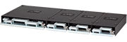
Sensor adapter collects all sensor data as a central medium, and then transfers the data to all FMD-3200/3300 ECDIS and FCR-2xx9 chart radar in the system. Since the sensor adapter can be extended to all sensors in the coverage system, the wiring of ECDIS sensor/radar interface can be greatly reduced.
Navigation sensors can directly access eight serial I/O ports of ECDIS processor.
Sensor adapters are required in the following cases
Sharing sensor data in multi-network ECDIS and radar systems.
The number of sensors accessed exceeds the number of ports of the processor (8 serial I/O ports, 1 digital input port and 6 digital output ports), and/or
Networked sensors, including analog sensors.
To integrate ship-borne sensors into navigation network, sensor adapters can be connected to switch hub HUB-100, where sensor data can be distributed to the entire network. Alternatively, multiple sensor adapters can be connected via Ethernet to integrate shipborne sensors for Shipborne networks.
系统图 型号:FMD-3200/3300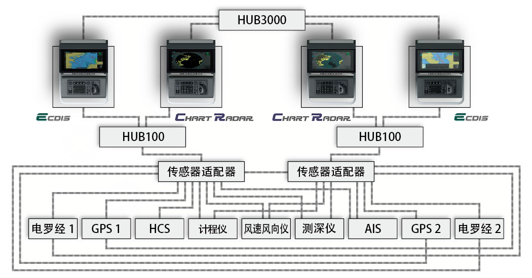
ECDIS Control Unit
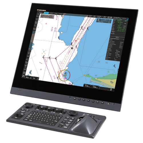
Operators can use ECDIS control unit RCU-024 or trajectory ball control unit RCU-026 to control FMD-3200 and FMD-3300. All the functions of ECDIS can be used by using trajectory balls, rollers and left/right clicks.
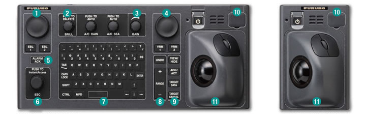 ECDIS control unit RCU-024 / Trajectory ball control unit RCU-026
 Press "EBL 1" and "EBL 2" to start/close the corresponding EBL; rotate the encoder to adjust the active EBL.
 Rotate to adjust the brightness level of the Old Field Display; press to select "Display Palette".
 Rotate to adjust radar gain (when chart and radar overlay display).
 According to "VRM 1" and "VRM 2", start/close the corresponding VRM; rotate the encoder, adjust the active VRM.
 Confirm the generated alert.
 Rotate to select the item in the shortcut button bar; press to confirm the item selection.
 QWERTY full keyboard allows easy entry of route, event and route point names.
 The following corresponding functions are assigned for each key:
| Undo | Undo |
|---|---|
| Range | Selection of Chart scale |
 The following corresponding functions are assigned for each key:
| View/Hide | Show/Hide Shortcut Button Bar and Route Information Window |
|---|---|
| ACQ/ACT | Enabling Selected Active AIS Targets |
| Target data | Display detailed target data for selected TT/AIS |
| Target cancellation | Hibernate selected active AIS targets |
 Chart updating, import/export, WP/route, USB port for user settings.
 Trackball module
The trajectory ball module consists of four parts, each of which has the following functions:
| Track ball | Move the cursor and select the target |
|---|---|
| Left click | Perform/validate actions related to the selected target |
| Right click | Display context menu when cursor appears in display area, cancel operation on selected target |
| Roller | Select menu items |
|
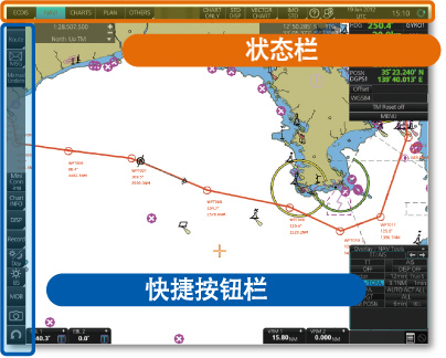
FMD-3200/FMD-3300 user interface is centered on carefully organized operating tools: status bar and shortcut button bar.
The status bar at the top of the screen contains information related to the operation status, that is, MFD operation mode, ECDIS operation mode and so on. The shortcut button bar on the left side of the screen contains all tasks (functions/operations) corresponding to the currently selected ECDIS mode of operation. These tools deliver straightforward task-based operations through which operators can quickly perform navigation tasks without entering complex menu trees.

The buttons in the status bar and shortcut button bar indicate hidden action/task options in the sublayer, which can be activated by left-clicking the button.
In this way, operators can quickly access related tasks.

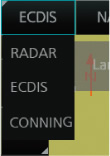 Click this button to open the MFD mode selector.

Three ECDIS modes of operation can be quickly accessed by using these three buttons:
"Monitoring Model", "Chart Maintenance Model" and "Planning Model". When the mode of operation is selected, the upper part of the shortcut button bar will change accordingly, and the tasks specific to each ECDIS mode of operation can be accessed quickly.

Click Playable Log。

When you press the left key for a long time, only the chart will be displayed.

Click to restore IMO standard display.

Click to set priorities for displaying charts.

IMO BASE (IMO Foundation), IMO STD (IMO Standard) or IMO-ALL (IMO-All)

Click to display the operation manual, ECDIS program number and system information.

Click Select, Manage, and Set User Profiles.
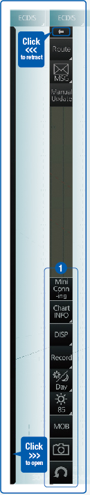
Click on the shortcut button bar  The shortcut button bar is retracted to the edge of the screen. Click on the hidden bar at the edge of the screen and the shortcut button bar will be restored to its original shape.
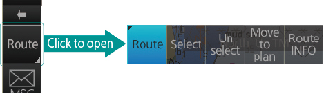
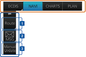
The top of the shortcut button bar contains a list of available tasks/functions specific to each selected ECDIS mode of operation, so that tasks/functions to be performed can be accessed quickly. The menu items at the top of the shortcut button bar vary with the mode selected, while the bottom of the shortcut button bar of all modes remains unchanged (except Mini Conning, which is available in "Monitoring Mode" and "Planning Mode".
Detailed information can be displayed when the mouse moves to various icons on the left.

Click to display and hide "Mini Conning Display" only in "Monitoring Mode" and "Planning Mode".


Click to view various data about the chart currently displayed, depending on the type of chart displayed.

Click to open the chart view date setting window.

Click to view an overview of ECDIS chart symbols.

Click to log user/location events to event logs, and access and view various logs, including: navigation logs (details logs, itinerary logs and chart usage logs), target logs and alert logs.

Click to select a palette (color and brightness settings for screen display) that matches the surrounding lighting conditions.

Click to open the brightness level adjustment window of the display screen, in which the brightness level can be adjusted manually (through the meter) or automatically (by clicking the automatic brightness adjustment button next to the brightness meter).

Click to enter the Man Overboard tag into the chart.

Click to intercept the screenshot.

Click to undo/redo the history operation.


Click the settings window for chart/symbol display and chart alerts.

Click to split the screen into two parts (two-way split screen).

Click to display "Admiralty Information Coverage (AIO)"

Click to activate the screen keyboard.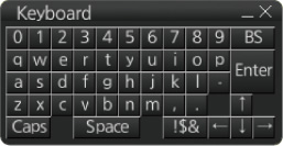
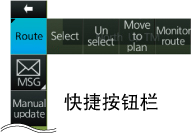
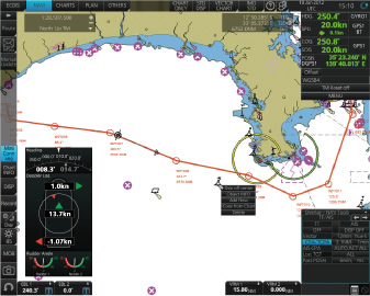
The ship behavior related to the planned route can be monitored in the "monitoring mode". All kinds of navigation monitoring tools can be merged into the shortcut button bar.
 |
|
 |  AIS/NAVTEX 消息对话框Click to open the "AIS/NAVTEX Message Menu" window where operators can process AIS/NAVTEX messages, i.e. send, view and delete messages. |
 | Click to open the manual update menu window. The operator can update the electronic chart by manually inserting chart update symbols according to navigation announcements, NAVTEX warnings, etc. The chart needs to be updated manually to ensure that it remains up to date. When the official chart updates contain changes to manual updates, the operator can delete the manual updates symbol in the manual update menu window.
|
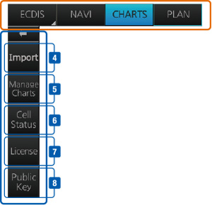
"Chart Maintenance Mode" allows operators to use charts in their processing systems.
 | Click to start automatically installing chart data in chart CD or DVD ROM. |
 | Click on the manageable chart, i.e. grouping chart units by purpose, deleting unnecessary chart units, etc. |
 | Click to view the chart catalogue and display general information about the charts installed in the system, namely coverage, license status, availability and other status information. |
 | 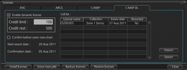 Chart License Menu WindowClick to open the chart license menu window, where the operator can view the license status of the installed chart. In addition, the operator can install, backup, restore and export chart licenses in the same menu window. |
 | Click to open the Public Key management window. Users can change the public key (used to verify the source and integrity of chart data used in ECDIS). |
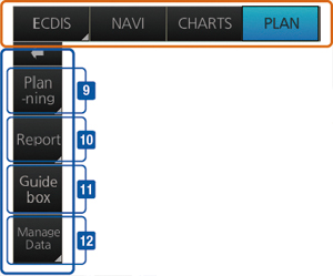
Operators can generate and edit route planning and user charts in "plan mode". In addition, you can view various detailed reports generated by ECDIS on planned routes and user charts. All these tasks can be accessed from the shortcut button bar.
 |  | Route planning Left-click "Route" to open the route planning menu window. Operators can use trajectory balls to enter route points directly on charts. After entering the route point, the operator can edit the name, steering mode, radius, channel restriction and other parameters of the route point in the menu window.  Route Planning Dialogue Box |
 | Creating User Charts Clicking "User chart" will display user chart tools (palette and menu window), which can be used by operators to create user charts. User charts are layers of markers and lines that can be drawn and overlapped on the charts. It is used to indicate security-related areas and objects. 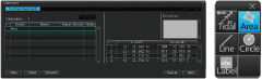 User Chart Tool | |
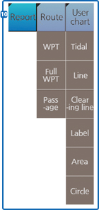 | Quick access to various reports You can view directly from the shortcut button bar the route reports on direct access points and channel plans, as well as user chart reports on tides, lines, user input targets and user-defined areas. | |
 | When the cursor is dragged, the navigation box immediately informs the operator of the distance and orientation between the last route point and the cursor position.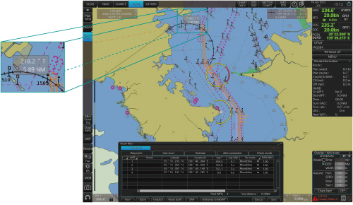 Route Planning Display | |
 | Click to open the data management window for routes and user charts, where you can delete the selected routes and user charts. | |

WeChat Official Account
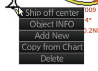 Context menu